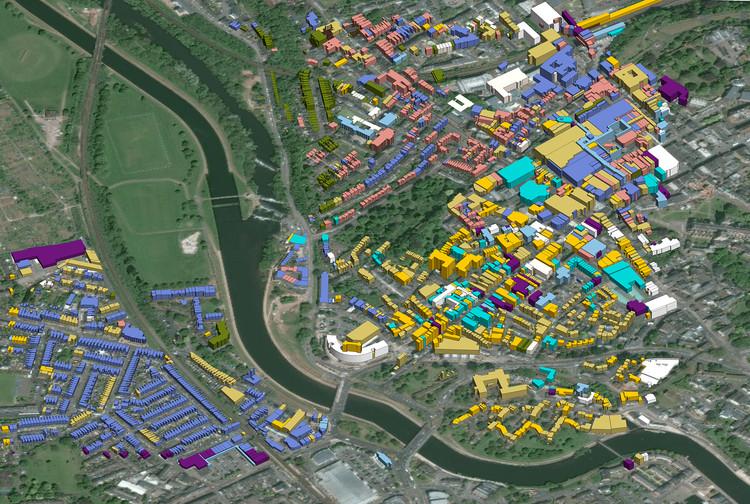
Architects, landscape architects, and planning professionals have been working with GIS data for many years to great success in Vectorworks’ BIM workflows. Much of this work has involved georeferenced Shapefiles (SHP), Drawing Interchange Formats (DXF), and image files (JGW, BPW, TFW, etc.). Though georeferencing makes sense as a solution for aligning GIS data in a BIM environment, users did not immediately expect that it would also be the solution to maintaining accurate positioning of site CAD and BIM files within the project. This article will describe how users are finding success by incorporating georeferencing in Vectorworks Landmark to better collaborate with the external and internal project participants.
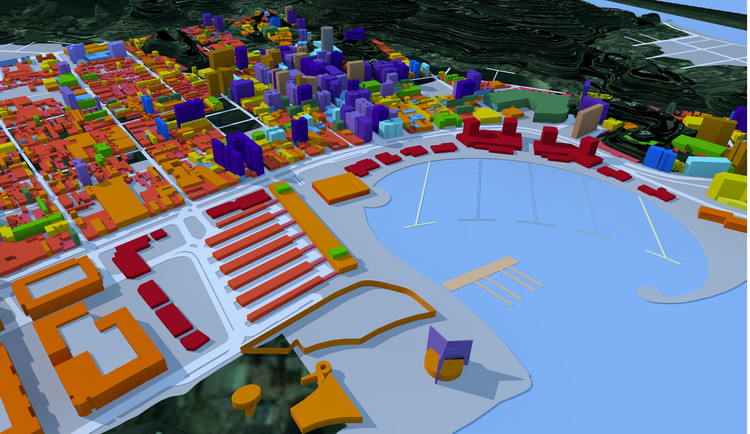
Many haven’t been required to think about geometry’s coordinate location unless the object involved a property line, ownership boundary, roadway layout, or similar feature that required coordinate layout to meet the legal or buildable description of the entities.
We are all accustomed to the positioning system X and Y, also known as Easting and Northing. With projects large enough to concern the earth’s surface curvature, though, the challenge is that general coordinate geometry relates only to flat surfaces. So, we have to consider how to translate/transform real-world locations and imagery to a flat 2D surface.
ESRI’s Understanding Map Projections explains the convention of latitudes and longitudes. For a quick understanding, imagine angles drawn from the center of the earth to the surface. The lines connecting north pole to south pole are longitude lines, while those circumscribing the earth easterly and westerly are latitude lines. This is the Geographic Coordinate System (GCS), which is not applicable to flat mapping. Those mappings have 3 general options for transforming GCS to a Projected Coordinate System (PCS): Conical, Cylindrical, and Azimuth. This helps to transfer to flat mapping and the conventions of X and Y; but of course that leads to some skewing. Fortunately, certain GIS map projections utilize these conventions.
So, why does knowing the PCS matter to architects, landscape architects, and other site design professionals if they are not trying to use GIS? The meets and bounds, property maps, plot plans, and base map files received from survey and civil engineers are why knowing PCS matters. Site layout plans typically provide a point of beginning and legal demarcations which relate directly to a known state/regional/country plane, and this becomes the PCS for their file. If firms expect to use and trade the file among other collaborators as the standard basemap or background, then using the same PCS will aid in keeping the site designers’ work in line with everyone else’s.
In the BIM application Vectorworks, georeferencing enables easy location of each project’s proper coordinate system through a Coordinate Reference System (CRS) lookup. Figure 1.1 depicts a CRS name being chosen.
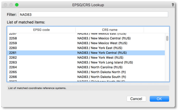
Users can enter projection information in the Georeferencing dialog box; or, when a projection is picked in the selection pull down menu, the predefined projection codes are automatically entered. The option for “Well Known Text” is more open to the specific coordinate system site designers may need to choose. In cases where such a CRS is not readily found, other resources such as EPSG.io can help to find the CRS, or its EPSG code number.
Aside from utilizing the right CRS, users find the overarching issue of BIM and CAD file collaboration relates to internal and user origins, which are vital to understand when dealing with project coordinates a large distance from 0,0. Like with any CAD or BIM application, keeping drawing and modeling close to the file’s internal origin ensures better accuracy and performance. As a site designer starts a project file in Vectorworks or imports a file, they will note that the center (internal origin) of a new Vectorworks drawing has fixed coordinates of 0,0, which do not change.
There is also a User Origin, which is coincidently located at 0,0. Though the initial coordinate for the Internal Origin is 0,0, when the User Origin is in a different location from the Internal Origin, the drawing coordinates of the Internal Origin will then display relative to the User Origin. Different from the Internal Origin, Vectorworks’ User Origin can change from its initial position. Since users will want to make sure their project sits closer to the Internal Origin, and recognizing that the base plan or survey imported from other collaborators may be far from 0,0, this means that the imported or referenced DWG file will need to move closer to the Internal Origin.
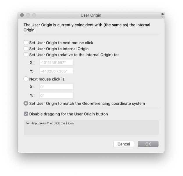
To maintain correct coordinate positioning, the User Origin must also move with the same coordinate direction and distances as the file moves. For example, if the project needs to move -2 million for its X coordinate and -3 million for its Y coordinate, then so should the User Origin. Entering this in the dialog, as shown in figure 1.2, is the most accurate way to accomplish this. To be clear, the User Origin will have moved by those large distances, but the User Origin now defines 0,0; the Internal Origin now would show its coordinates as the large values (but still be the center of the file).
When importing a DWG file of the project site from a survey or civil engineer, users are encouraged to acknowledge the DWG prompts and descriptions for each of the Import Location Options. Particularly, the option to Align with Internal Origin is recommended for the first file import and the Align with User Origin for all subsequent imports. This option should only be used after the User Origin is set.
With recognition that an established base point is still necessary, Vectorworks Landmark makes georeferencing easier with a dedicated built-in toolset. Users can feel confident in their ability to exchange georeferenced CAD and BIM files.
Watch a recorded presentation on better collaboration using georeferencing.

